This information pertains to Vernier (BTD) Photogates. Photogate (
For information about using Go Direct Photogates, see How can I use Go Direct Photogates (GDX-VPG) to time the Science Olympiad Scrambler event?
The Science Olympiad Scrambler event suggests using laser photogates to time the scrambler devices. The devices must traverse an 8-meter course. Our photogate cables do not reach that far, but they can be modified. These instructions are for using a photogate with a laser, making an extra-long cord, and for timing using Vernier software.
Part 1: Using Vernier (BTD) Photogates with a laser
Materials available from Vernier:
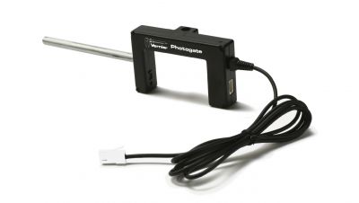
2 –Photogate (
2 –Laser Pointer (
3 –Digital Extension Cable (
1 –LabQuest 3 (
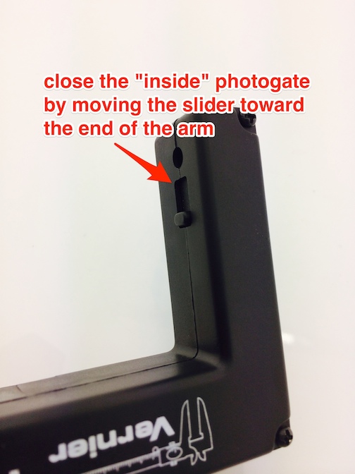
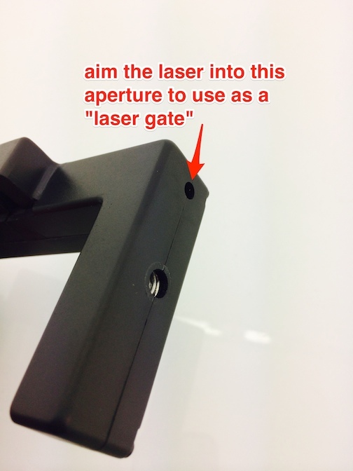
You will need two photogates and two class 2 lasers. Science Olympiad prohibits the use of class 3 or higher lasers. Many commercial laser pointers will work. Each photogate will have to be securely mounted at the correct height (see http://vnr.st/xe1d ) and will need its own laser pointer. See http://vnr.st/xff8 or http://vnr.st/xf3f


Part 2: Making the extra-long cord
There are several ways to make the extra-long cord you need.
Option 1 – You can purchase three Digital Extension Cable (
- Attach one to one of the photogates’ cable and attach two to the other photogates’ cable.
- Connect both photogates to your interface so that the photogate at the beginning of the course is connected to DIG 1 and the photogate at the end of the course is connected to DIG 2.
Note: The software measures the times based on the order the photogates are discovered when the software launches. If the software is already running, the order you connect the sensor is used.
Option 2 – Purchase 20 feet of RJ-12 (6P6C US telephone wire) and a double-female RJ-12 connector.
- Connect one end of the RJ-12 wire to a photogate. (Make sure you purchase 6-wire phone cable; 4-wire phone cable will not work.)
- Connect the double-female connector to the other end of the wire.
- Connect one photogate cable (that came with the photgate) to other side of the double-female connector.
- Connect both photogates to your interface so that the photogate at the beginning of the course is connected to DIG 1 and the photogate at the end of the course is connected to DIG 2.
Note: The software measures the times based on the order the photogates are discovered when the software launches. If the software is already running, the order you connect the sensor is used.
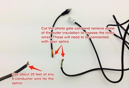
Option 3 – Splice 6-conductor wire into an existing BT Photogate Cable (
- Purchase (at a hardware or hobby store) enough 6-conductor wire to splice into a standard photogate cable. You will need a little more than 6 meters of wire (20 feet will be plenty).
- To be sure you are connecting the wires correctly, you may want to connect one wire at a time, such as red at both ends, orange at both ends, yellow at both ends, etc. We recommend soldering the connections for best results, and you will have to insulate the joints from touching each other.
- Connect both photogates to your interface so that the photogate at the beginning of the course is connected to DIG 1 and the photogate at the end of the course is connected to DIG 2.
Note: The software measures the times based on the order the photogates are discovered when the software launches. If the software is already running, the order you connect the sensor is used.

Part 3: Collecting data
Using LabQuest App (original LabQuest, LabQuest 2, or LabQuest 3)
- Connect the photogates to the LabQuest’s digital (DIG) ports as follows:
a. Connect the photogate at the beginning of the course to DIG 1.
b. Connect the photogate at the end of the course to DIG 2.
Note: On LabQuest 2, the DIG 1 and DIG 2 ports are under a black rubber flap next to the power button. See: Why won't my Motion Detector (or other digital sensor) plug into the channels of my LabQuest 2? - Tap the “Mode:” box on the right side of the LabQuest screen and adjust the photogate timing settings as follows:
a. Change the Photogate Mode from “Motion” to “Pulse.”
b. Enter the correct distance into the “Distance between gates” box.
c. Change the setting to end data collection after 4 events. - When you are ready to time a run, first tap the Collect button on LabQuest. Then signal that the contestant can start their vehicle. Once the vehicle has passed through both photogates, the time of travel and the average velocity of the vehicle will be shown to the right of the graphs.
Using Logger Pro 3
- Connect the photogates to the LabQuest’s digital (DIG) ports as follows:
a. Connect the photogate at the beginning of the course to DIG 1.
b. Connect the photogate at the end of the course to DIG 2. - Launch the Logger Pro 3 software and open the file “Pulse Timer-Two Gates.cmbl” found in Experiments > Probes & Sensors > Photogate.
- When you are ready to time a run, first click the Collect button in Logger Pro 3. Then signal that the contestant can start their vehicle. Once the vehicle has passed through both photogates, the time of travel will be shown in the data table.
Using Graphical Analysis App or Graphical Analysis Pro
- Connect the photogates to the LabQuest’s digital (DIG) ports as follows:
a. Connect the photogate at the beginning of the course to DIG 1.
b. Connect the photogate at the end of the course to DIG 2. - Launch Graphical Analysis and connect to your interface. The photogates should automatically identify.
- Click or tap Mode and change the settings as follows:
a. Change the Measurement to “Timer or Period – Time between gates”
b. Click or tap DONE. - Click or tap View Options and select Table.
- When you are ready to time a run, first click the Collect button in Graphical Analysis. Then signal that the contestant can start their vehicle. Once the vehicle has passed through both photogates, the time of travel will be shown in the data table.
Related Links:
How do I set up wired Vernier Photogates (VPG-BTD) for data collection with Logger Pro 3?
How do I set up wired Vernier Photogates (VPG-BTD) for data collection using LabQuest App?
How do I set up wired Vernier Photogates (VPG-BTD) for data collection using Graphical Analysis and Graphical Analysis Pro?

