Troubleshooting
- Primary Test: Plug the probe into an interface and run the data collection program. Use wire leads to connect the probe to a DC supply with a known resistance. Use a voltage probe or voltmeter to measure the voltage. Compare the measured current against the theoretical reading. Note: We recommend a DC battery for this test, since some variable power supplies may not deliver clean DC voltage.
- Secondary Test: The sensor contains a replaceable 10 A fuse. If the sensor stops measuring current, you may need to replace a blown fuse. Turn the sensor over and remove the four screws on the back. The fuse can be seen from the top. Use a small screw driver to remove the fuse. Insert a replacement. One replacement fuse has been included with the sensor. Additional replacements, in packs of five, can be purchased from Vernier.
Replacement Fuse for High Current Sensor (FUSE-HCS )
Additional Troubleshooting
- Why is my High Current Sensor is giving inconsistent readings?
- How do I measure currents larger than 0.6 amperes?
- Why is my High Current Sensor is giving inconsistent readings?
- How can I measure currents outside the range of the Vernier Current Probe?
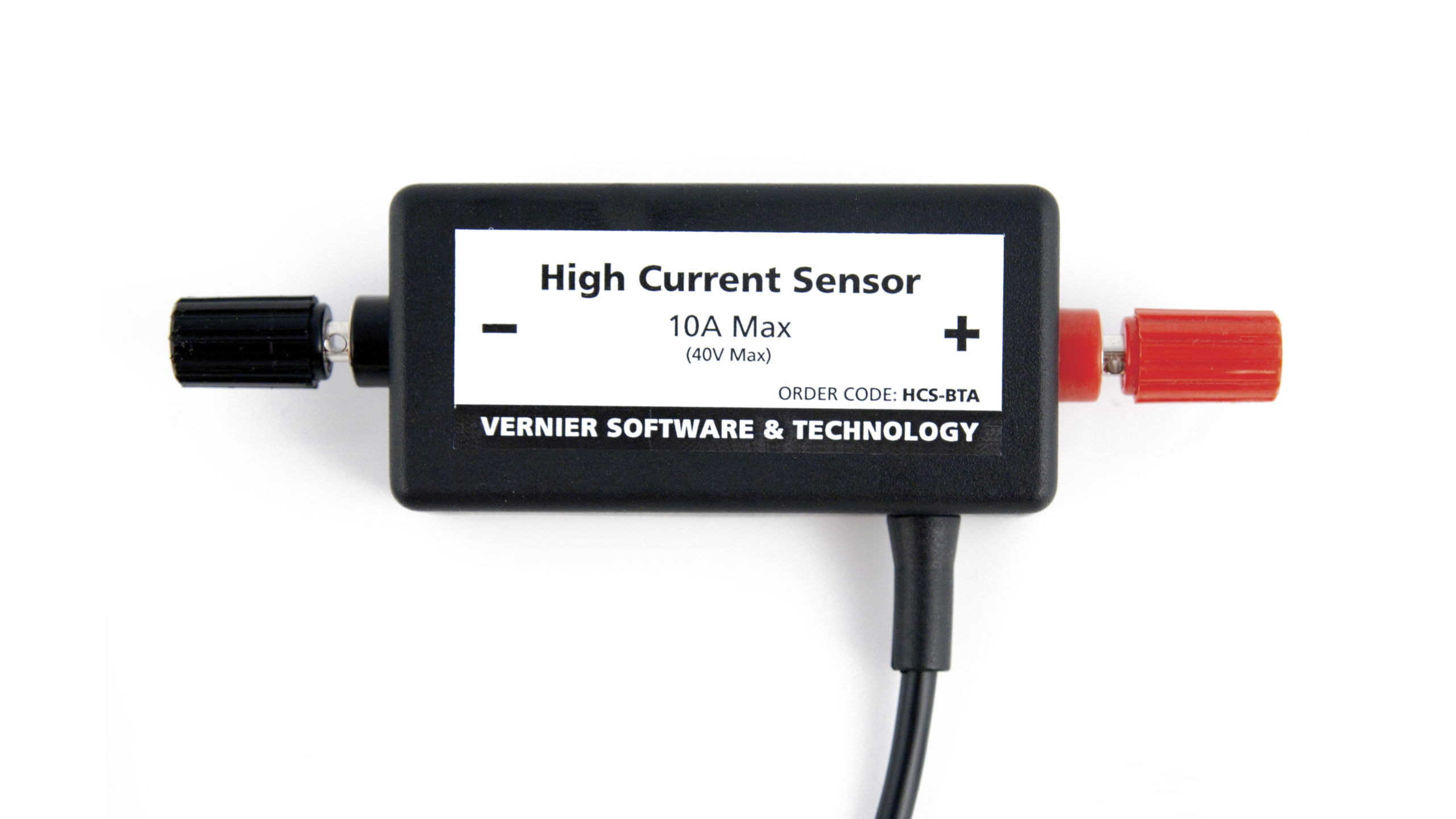
Specifications
- Resolution
⚬ 12-bit: 4.9 mA
⚬ 13-bit: 2.4 mA - Sensor range: ±10 A
- Maximum voltage input: ±40 V
- Replaceable fuse Current: 10 A
- Calibration equation
⚬ slope = 4.51 A/V
⚬ intercept = -11.31 A
Calibration
Calibrating the sensor is usually not needed prior to use. You may want to zero the sensor through the software; connect the sensor’s terminals with a single wire/alligator clip first. When measuring currents that are less than 0.6 A, we recommend our Current Probe (
Related Products
- Replacement Fuse for High Current Sensor (
FUSE-HCS ) - Current Probe (
DCP-BTA ) - Go Direct® Current Probe (
GDX-CUR ) - 30-Volt Voltage Probe (
30V-BTA ) - Differential Voltage Probe (
DVP-BTA ) - Go Direct® Voltage Probe (
GDX-VOLT )