Truss Tester Accessory User Manual
Order Code: VSMT-TRUSS
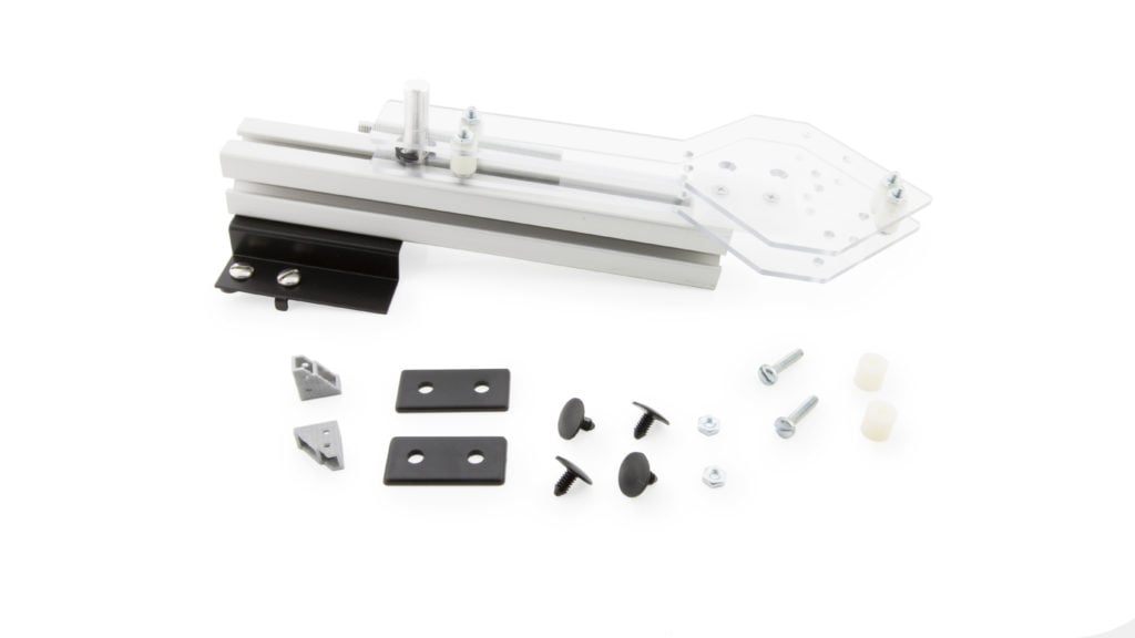
The Truss Tester Accessory is designed for use with the Vernier Structures & Materials Tester (VSMT) or the Go Direct Structures & Materials Tester (GDX‑VSMT). The Truss Tester Accessory holds a single truss upright and provides the means to apply a force to the truss, while measuring that applied force and the displacement of the loaded portion of the truss.
The truss holder consists of a pair of side panels that hold the truss being tested and prevent the truss from tipping over. A support post connects to the top rail of the Structures & Materials Tester with standard 80/20® fittings. The truss holder is connected to the support post through a plastic bearing shoe that glides up and down in the grooved post. The truss holder also connects to the load cell (force sensor) with a 4 in. threaded rod that screws into the top of the load cell. The Truss Tester Accessory applies the force to the truss through 1/2 in. diameter spacers that can be positioned for a variety of loading locations.
Note: Vernier products are for educational use only.
What's Included
- Bracket assembly with a grooved 80/20 post
- Truss holder assembly consisting of
- Polycarbonate side panels, with bearing shoe (2)
- 1/2 in. spacers, an aluminum coupling pin (4)
- 4 in. 1/4‑20 threaded rod (1)
- Bag of parts, including
- Truss corner brackets (2)
- Replacement 80/20 double-hole end caps (2)
Additional 1/2 in. spacers with hardware (2)
Assembly
Refer to the Truss Tester Accessory Assembly Instructions that shipped with the product. These are also available online at www.vernier.com/vsmt-truss-assembly
Using the Product
The Truss Tester Accessory comes in two parts: the bracket and support post that attaches to the Structures & Materials Tester and the truss holder that slides in the post groove and connects to the VSMT load cell.
- Remove one crossbar on the structures tester by loosening the attachments and sliding the crossbar off the long beams. Remove the two end caps in order to slide the crossbar off the long beams.
- Slide the bracket and grooved 80/20 post onto the structures tester support beam and center the device above the load cell. Do not tighten the screws at this time.
- Slide the polycarbonate truss holder onto the grooved 80/20 post and lower it so the threaded rod can be attached to the load cell. Ensure the rod is threaded firmly into the coupler on top of the load cell. Tighten the screws that secure the bracket to the support beam.
- Reattach the crossbar. Adjust the crossbars to the appropriate width and secure them. Replace the end caps if desired.
- Adjust the height of the Truss Tester Accessory with the displacement wheel on the structures tester. To adjust the height of the contact point, you may need to thread more of the rod through the coupling shaft, reposition the 1/2 in. spacers, or both.
- Place the truss between the polycarbonate side plates and adjust the Tester height to make contact with the truss.
- Wear safety glasses. Viewing is best accomplished looking head on. Broken trusses tend to eject material to the sides.
- Connect the structures tester to an appropriate interface (if required) and software platform. Zero the sensors in the software. You are now ready to test the strength of your truss and collect data.
Specifications
The Truss Tester Accessory is designed for maximum 1/2 in. wide material. It is optimized for 1/4 in. square balsa, so not to exceed VSMT force limitations.
Safety
Wear safety glasses when testing trusses. Broken trusses tend to eject material to the sides.
Care and Maintenance
Be mindful that your truss doesn't exceed the maximum height accommodated by the truss holder (about 18 cm). The structures tester has a 0–1000 N load cell operating range. Forces above 1300 N may result in permanent damage to the load cell.
How the Accessory Works
The Truss Tester is an excellent starting point for conducting a bridge building activity. Students can evaluate how trusses fail and what they can do to improve their performance. They may discover that the trusses usually fail in a particular way and that including a brace at the point of failure provides a significant improvement in its ability to sustain a load. They can also test more complex structures, such as a bridge or crane.
The truss tester was designed for use with 1/4 in. square balsa wood or 3/32 in. balsa planks up to 3/4 in. wide.
Note: Other materials may work, but these materials are readily available and are known to work with the design parameters of the Truss Tester and the Structures & Materials Tester.
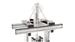
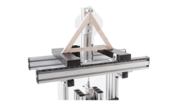
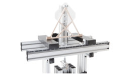
The crossbars on the Structures Tester were set for a 16 cm span to carry a truss width of 18–20 cm in order to provide a range of potential angles that will fit within the truss holder dimensions.
The Truss Tester Accessory comes with two corner brackets that are useful in quickly constructing triangular trusses. The brackets slide onto the bottom member and can be held in place with small blocks of balsa wood, or gussets.. The angled members can be cut to length and allowed to push against each other with or without glue or gussets.
An alternative to using the brackets is to glue the joints together. Lap joints with lots of surface area overlap work best, especially when trying to optimize truss design. Hot gluing balsa, with a little practice, provides a quick and strong bond.

Tips for integrating this accessory with the Structures & Materials Tester can be found at http://www.vernier.com/vsmt
Troubleshooting
For troubleshooting and FAQs, see www.vernier.com/til/3595
Repair Information
If you have followed the troubleshooting steps and are still having trouble with your Truss Tester Accessory, contact Vernier Technical Support at support@vernier.com or call 888-837-6437.
Warranty
Warranty information for this product can be found on the Support tab at www.vernier.com/vsmt-truss/#support
General warranty information can be found at www.vernier.com/warranty
Contact Support
Fill out our online support form or call us toll-free at 1-888-837-6437.

