Constant Current System User Manual
Order Code: CCS-BTA
The Constant Current System is a DC power source with a built-in current probe designed for use in electrochemistry experiments. The user can set the current by tuning the dial with the system capable of delivering up to 0.6 A. The following is a partial list of activities and experiments that can be performed using this sensor.
- Electroplating and Faraday’s law
- Electrolysis
- Determining Avogadro’s number
What’s Included
- Constant Current System
- LabQuest Power Supply
Compatible Software and Interfaces
Choose a platform below to see its compatibility requirements.LabQuest
Interface LabQuest App LabQuest 3 Full support LabQuest 2 Full support LabQuest Full support Computers
Software Interface Graphical Analysis Graphical Analysis (Web App) Logger Pro (discontinued) Logger Lite (discontinued) LabQuest Mini Full support Full support Full support Full support LabQuest 3 Full support Full support Full support Incompatible LabQuest 2 Full support Full support Full support Full support LabQuest Stream Full support 1 Full support 1 Partial support 2 Full support 1 Go!Link Full support Full support Full support Full support LabQuest Full support Full support Full support Full support LabPro Incompatible Incompatible Full support Full support Compatibility Notes
Chromebook
Software Interface Graphical Analysis (Web App) LabQuest Mini Full support LabQuest 3 Full support LabQuest 2 Full support LabQuest Stream Full support 1 Go!Link Full support LabQuest Full support Compatibility Notes
iOS
Software Interface Graphical Analysis Graphical Analysis GW LabQuest Stream Full support Full support LabQuest 3 Full support 1 Full support 1 LabQuest 2 Full support 1 Full support 1 Compatibility Notes
Android
Software Interface Graphical Analysis Graphical Analysis GW LabQuest Stream Full support Full support LabQuest 3 Full support 1 Full support 1 LabQuest 2 Full support 1 Full support 1 Compatibility Notes
Arduino
Software Interface Arduino Vernier Arduino® Interface Shield Full support LabVIEW
Software Interface NI LabVIEW SensorDAQ Full support Vernier myDAQ Adapter Full support 1 Go!Link Full support LabQuest Mini Full support LabQuest Stream Full support LabQuest 3 Full support LabQuest 2 Full support LabQuest Full support Compatibility Notes
Texas Instruments
Software Interface EasyData DataMate TI-84 SmartView DataQuest TI-Nspire Software EasyLink Full support 1 Incompatible Full support 2 Full support Full support 2 CBL 2 Full support 3 Full support 3 4 Incompatible Incompatible Incompatible LabPro Full support 3 Full support 3 4 Incompatible Incompatible Incompatible TI-Nspire Lab Cradle Incompatible Incompatible Incompatible Full support Full support Compatibility Notes
Quick Start
- Plug the sensor into the interface (LabQuest 3, LabQuest Mini, etc.).
- Connect the interface to your device.
- If using USB, connect to the USB port on your computer.
- If using Bluetooth® wireless technology, click your interface type and then select your device.
- Prepare for data collection:
- Vernier Graphical Analysis®: Launch the app, if necessary, and click Sensor Data Collection.
- LabQuest® App: Choose New from the File menu.
The software will identify the sensor and load a default data-collection setup. You are now ready to collect data.
Need Additional Information?
Visit the following link:
www.vernier.com/start-lq-sensor
Note: Vernier products are for educational use only.
Using the Product
The Constant Current System can be used instead of the Current Probe and DC power supply for the following experiments from Advanced Chemistry with Vernier:
- Experiment 21 (AP Lab 21): Electroplating
- Experiment 31: Determining Avogadro’s Number
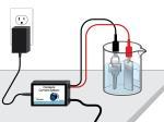
An example setup of an electroplating experiment using the Constant Current System is shown in Figure 1.

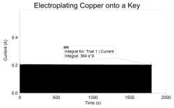
The graph in Figure 2 displays the constant current measured during the electroplating of copper onto a key. The total charge passed through the electrolytic cell can be determined by calculating the integral of the graph of current vs. time.

Calibration
You do not have to perform a new calibration when using the Constant Current System. It is calibrated before it is shipped. If you wish to perform your own calibration, use the 2-point calibration procedure found in all Vernier data-collection programs. The output of this system is linear with respect to the measurement. A digital ammeter or multimeter is required to perform a calibration
- First Calibration Point: Disconnect the output terminals (red and black clips) from everything so that no current is flowing. Enter zero as the value for
Reading 1. - Second Calibration Point: Set up the ammeter or multimeter to measure current. Connect the clips on the Constant Current System to the ammeter so that current from the Constant Current System is flowing through the ammeter. Turn the dial on the Constant Current System clockwise to any position near the maximum. A current reading will be displayed on the ammeter. Enter this value as Reading 2.
Another option to consider instead of calibrating is “zeroing” the sensor. This option adjusts the calibration offset. This is done by disconnecting the red and black clips from everything so that no current is flowing, then choosing the Zero option in the data-collection software.
Specifications
|
Constant Current System range: |
0-0.6 A |
|
Linearity of the current sensor: |
0.1% |
|
Resolution |
0.18 mA |
|
Supply voltage: |
5 VDC |
|
Supply current (typical): |
9 mA |
|
Output voltage range: |
0–5 V |
|
Transfer function : |
Vout = 6.9(I) + 0 |
|
Calibration |
slope: 0.145 A/V intercept: 0 A |
|
Power Supply |
input: 100–240 Volts AC, output: 5 V, 1.5 A |
Care and Maintenance
Do not wrap the cable tightly around the sensor for storage. Repeatedly doing so can irreparably damage the wires and is not covered under warranty.
How the Constant Current System Works
The Vernier Constant Current System is a DC-coupled amplifier capable of delivering up to 0.6 A at 5 V DC. A current-sensing resistor allows monitoring of the output current through the sensor cable. When this output is connected to an analog input of LabPro, LabQuest 2, LabQuest, LabQuest Mini, Go! Link, SensorDAQ, EasyLink, CBL 2, or TI-Nspire Lab Cradle, a calibrated, current sensor is detected by software.
Current Conventions
The current will be indicated as positive if current flows from the positive (red) terminal to the negative (black) terminal as described by conventional current flow notation. Using electron flow notation, electrons flow out of the negative terminal through the circuit back to the positive terminal. The negative terminal is connected to ground via a power transistor and 0.1 W sensing resistor. The positive terminal connects to a 5 V power supply. The Constant Current System dial can be tuned to deliver up to 0.6 A with the voltage adjusting automatically (max 5 V). If the electrolyte resistance is too high, the 0.6 A may not be attained before the maximum of 5 V is reached.
Troubleshooting
For troubleshooting and FAQs, see www.vernier.com/til/2496
Repair Information
If you have followed the troubleshooting steps and are still having trouble with your Constant Current System, contact Vernier Technical Support at support@vernier.com or call 888-837-6437. Support specialists will work with you to determine if the unit needs to be sent in for repair. At that time, a Return Merchandise Authorization (RMA) number will be issued and instructions will be communicated on how to return the unit for repair.
Accessories/Replacements
| Item | Order Code |
|
LQ-PS |
Warranty
Warranty information for this product can be found on the Support tab at www.vernier.com/ccs-bta/#support
General warranty information can be found at www.vernier.com/warranty
Contact Support
Fill out our online support form or call us toll-free at 1-888-837-6437.

