Video Overview
Introduction
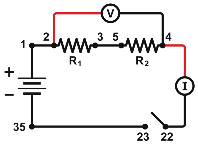
Components in an electrical circuit are in series when they are connected one after the other, so that the same current flows through both of them. Components are in parallel when they are in alternate branches of a circuit. Series and parallel circuits function differently. You may have noticed the differences in electrical circuits you use. When using some types of older decorative holiday light circuits, if one lamp is removed, the whole string of lamps goes off. These lamps are in series. When a light bulb is removed in your home, the other lights stay on. Household wiring is normally in parallel.
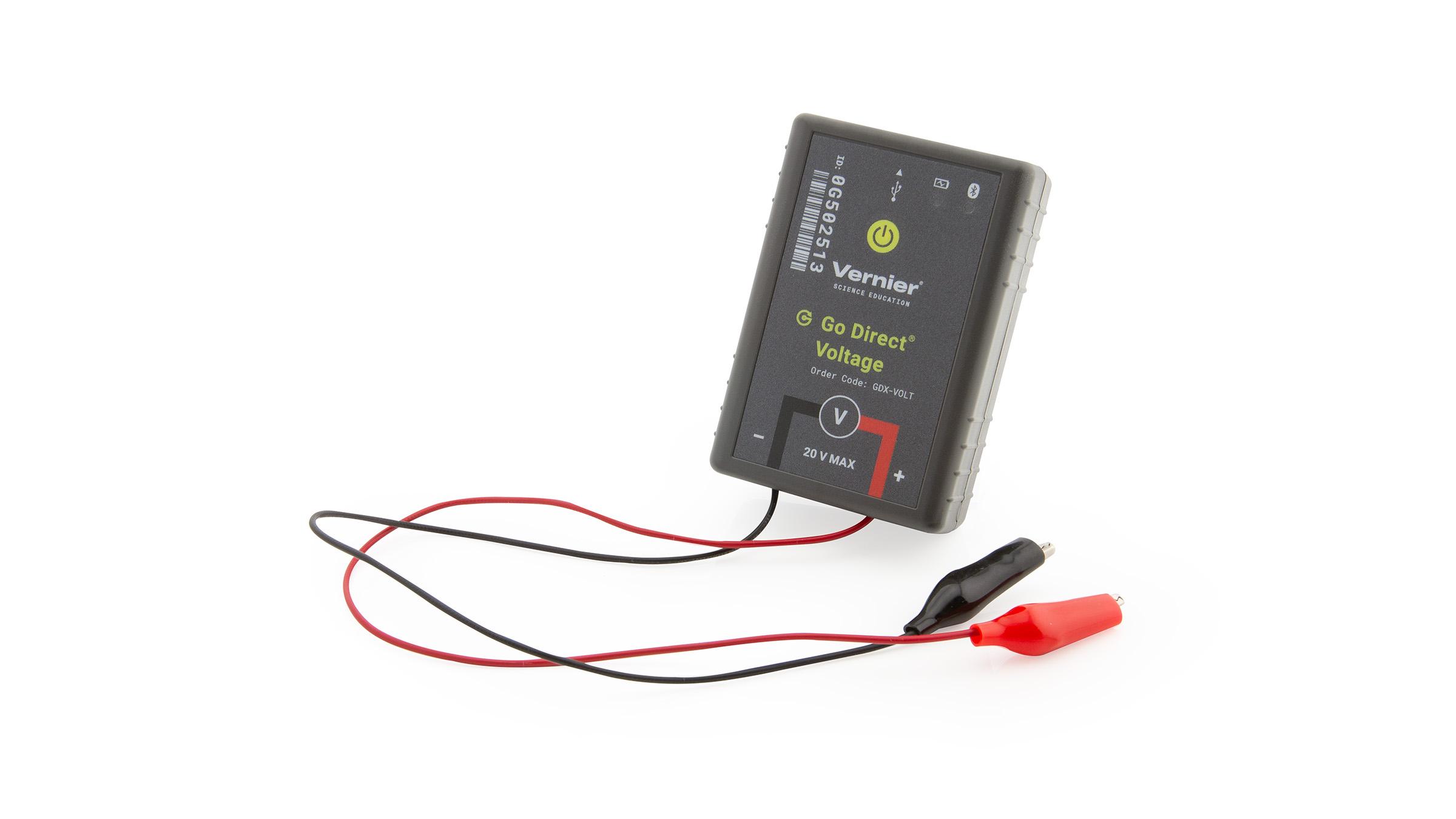
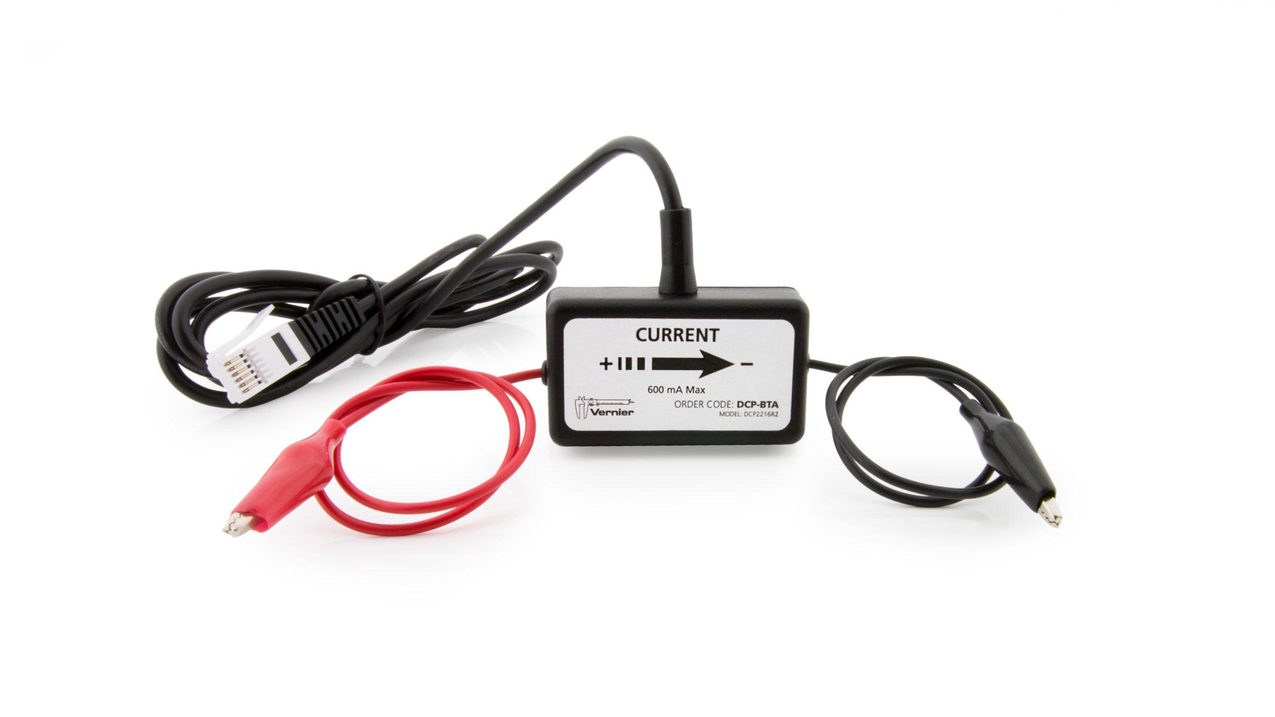
You can monitor these circuits using a Current Probe and a Differential Voltage Probe and see how they operate. One goal of this experiment is to study circuits made up of two resistors in series or parallel. You can then use Ohm’s law to determine the equivalent resistance of the two resistors.
Objectives
- To study current flow in series and parallel circuits.
- To study potential differences in series and parallel circuits.
- Use Ohm’s law to calculate equivalent resistance of series and parallel circuits.
Sensors and Equipment
This experiment features the following sensors and equipment. Additional equipment may be required.
Correlations
Teaching to an educational standard? This experiment supports the standards below.
- International Baccalaureate (IB) 2025/Physics
- The students should understand that circuit diagrams represent the arrangement of components in a circuit
- The students should understand the combinations of resistors in series and parallel circuits. Series circuits: I = I1 = I2 = Ω, V = V1 + V2 + Ω, RS = R1 + R2 + Ω, Parallel circuits: I = I1 + I2 + Ω, V = V1 = V2 = Ω, 1/Rp=1/R1+1/R2+Ω
Ready to Experiment?
Ask an Expert
Get answers to your questions about how to teach this experiment with our support team.
- Call toll-free: 888-837-6437
- Chat with Us
- Email support@vernier.com
Purchase the Lab Book
This experiment is #23 of Physics with Vernier. The experiment in the book includes student instructions as well as instructor information for set up, helpful hints, and sample graphs and data.


