There are two ways to connect Vernier sensors to Arduino. You can plug any standard Vernier sensor with a BTA or BTD connector directly into a Vernier Arduino Interface Shield or you make your own wired connections with a breadboard and one or more Vernier Protoboard Adapters.
The method you choose will depend on the complexity of your project. Be sure to use an Arduino board that operates at 5 volts; standard Vernier sensors will not work on 3.3-volt Arduino boards at this time.
Connecting Vernier Sensors to Arduino Using Vernier Arduino Interface Shield
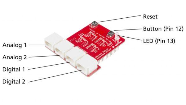
The Vernier Arduino Interface Shield plugs directly on top of an Arduino UNO board. It contains two analog sensor ports and two digital sensor ports labeled Analog 1, Analog 2, Digital 1, and Digital 2 from left to right. The Analog 1 and Analog 2 ports will accommodate over 80 Vernier analog sensors. The Digital 1 port is used for all digital sensors. The Digital 2 port is generally reserved for motors, LCD displays, and the Vernier Digital Control Unit (DCU). The shield also includes a reset button, a general-purpose button, and an indicator LED.
The Vernier Arduino Interface Shield is designed to work with any Arduino UNO R3 or R4, such as the Arduino UNO R4 WiFi.
Vernier Arduino Interface Shield
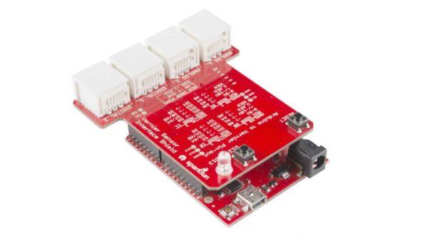
Vernier Arduino Interface Shield mounted on SparkFun RedBoard (RedBoard sold separately)
Connecting Vernier Sensors to Arduino Using a Breadboard
Another way to make the connection from the Arduino to Vernier sensors is to use our Analog Protoboard Adapter and Digital Protoboard Adapter.
These adapters were designed to plug into a breadboard using jumper wires to make connections from the breadboard to the Arduino pins. Choose the Analog Protoboard Adapter if you are using analog (BTA) sensors, the Digital Protoboard Adapter if you are using digital (BTD) sensors, or both if you will be using both types of sensors.
Our protoboard adapters have six pins. The pins are labeled on the adapters starting with the pin farthest from the tab on the socket. In order for Vernier library commands and sample sketches to work properly, be sure to make your connections between the breadboard and Arduino according to the pinouts listed below. Note these pin connections are identical to those used on the Vernier Arduino Interface Shield.
An Arduino connected to a Dual-Range Force Sensor using a Analog Protoboard Adapter
Analog Protoboard Adapters
Wiring a Single Analog Protoboard Adapter
SIG2 (Vernier BTA pin 1) to Arduino pin A1 (+/-10V output used by just a few Vernier analog sensors)
GND (Vernier BTA pin 2) to Arduino pin GND (ground)
ID (Vernier BTA pin 4) to Arduino pin A5 (not used by all sensors)
5V (Vernier BTA pin 5) to Arduino pin 5V (power)
SIG1 (Vernier BTA pin 6) to Arduino pin A2 (0-5V output used by almost all Vernier sensors)
Digital Protoboard Adapters
Wiring a Single Digital Protoboard Adapter
DIO0 (Vernier BTD pin 1) to Arduino pin 2 (function depends on sensor)
DIO1 (Vernier BTD pin 2) to Arduino pin 3 (function depends on sensor)
DIO2 (Vernier BTD pin 3) to Arduino pin 4 (function depends on sensor)
5V (Vernier BTD pin 4) to Arduino pin 5V (power)
GND (Vernier BTD pin 5) to Arduino pin GND (ground)
DIO3 (Vernier BTD pin 6) to Arduino pin 5 (function depends on sensor)
Wiring a Second Digital Protoboard Adapter
A second Digital Protoboard Adapter allows you to use two Vernier digital sensors at once or a digital sensor in conjunction with the Vernier Digital Control Unit (DCU) or the Vernier DCU by itself. Be aware that the VernierLib commands assume the sensor is plugged into the first adapter and the DCU is plugged into the second adapter.
DIO0 (Vernier BTD pin 1) to Arduino pin 6 (function depends on sensor)
DIO1 (Vernier BTD pin 2) to Arduino pin 7 (function depends on sensor)
DIO2 (Vernier BTD pin 3) to Arduino pin 8(function depends on sensor)
5V (Vernier BTD pin 4) to Arduino pin 5V (power)
GND (Vernier BTD pin 5) to Arduino pin GND (ground)
DIO3 (Vernier BTD pin 6) to Arduino pin 9 (function depends on sensor)