Which Model DCU Do I Have?
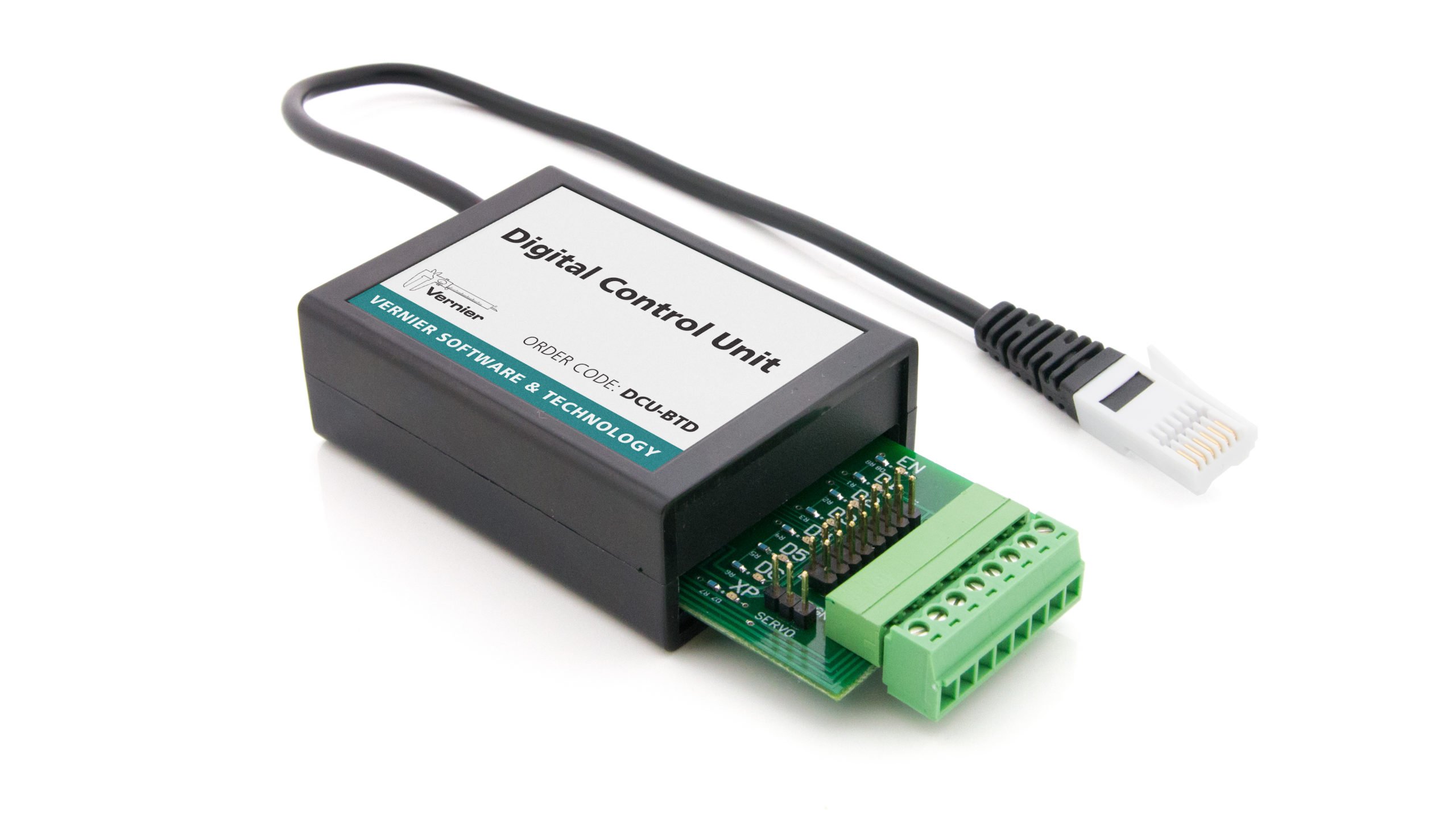
There have been three Digital Control Unit (DCU) models over the years. The current model (shown above) is black, rectangular, and has a screw terminal for each of the output lines, as well as separate pin connectors for a servo motor.
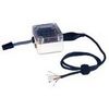
The previous models were white, square, and used a 9-pin serial connection for output. Students used a serial cable to connect the DCU to their circuits, with each wire in the cable corresponding to a different line/pin; each cable was labeled, identifying which color wire is connected to each line/pin.
General Information
Troubleshooting
- Primary Test: When you connect the DCU to an interface, does the green EN LED light up? Is external power supplied to the DCU? If you are using the current model, the blue XP LED should light up.
- Secondary Test: Does the DCU appear in the Set Up Sensor dialog box? Some Digital Control Units are not auto-ID. If your DCU has not been identified by Logger Pro and therefore does not show up under the DIG/SONIC button, you will need to set it up manually. To do this, click on the DIG/SONIC button and select Choose Sensor ▶ Digital Control Unit.
- Tertiary Test: When you test the output lines via Logger Pro, do the correct LEDs light up? In the Digital Out dialog box, you can test 3 output lines of the DCU by selecting the check box for Line 1 On, Line 2 On, and/or Line 3 On. The LEDs on the circuit board extending from the DCU will turn on when the line is on.
- Quaternary Test: Is your circuit set up correctly? Carefully review the circuit the DCU is turning on/off. Are all the connections secure? Are the components connected correctly (e.g., current flowing in the correct direction through diodes)? Does it require more power or current than the DCU can provide? If you are using an older 9-pin serial DCU, check to make sure that you have wired the correct line into your circuit.
Usage Tips
- In general, you can connect any electrical device that runs on DC electricity at a voltage that matches your power supply. The DCU output voltage can range from 5 to 12 V, depending on the DCU power supply. You can find thousands of different 5 to 12 V devices at most hobby and electronic stores, such as Mouser or DigiKey.
- The Digital Out feature is unable to scan all data at fast data-collection rates. This may mean that peaks or valleys that fall above or below the user-defined comparison value, but are of very short duration, might not activate or deactivate a line as configured. In such a case, LabVIEW provides higher rates and response times.
Additional Troubleshooting
- Where do I find electronic components for use with the Digital Control Unit (DCU)?
- Can I use the DCU with the CBL 2 or LabPro?
- When I set up my Digital Control Unit, the Digital Out option is disabled. What should I do? (Logger Pro)
- When I plug the radiation monitor into LabPro it stops working. (especially if you have been using DCU).
- Do you have an SDK or API for your sensors?
- What power supplies can I use with the DCU?
- National Instruments LabVIEW Troubleshooting and FAQs
- What sensors do not work with Go!Link?
- What are the differences between Logger Pro and Logger Lite?
- How can I control AC devices with the Digital Control Unit?
- Digital sensor does not automatically identify when connected to LabQuest after using the DCU.
- How fast does the DCU respond to data?
- Can I use Go Direct sensors with a Digital Control Unit?
- DCU Power Output Pack (DCU-POP) Troubleshooting and FAQs
- How do you wire a stepper motor to the DCU?
Specifications
- Output lines: 6 (a total of 3 lines with independent control)
- Max output current per line: 600 mA
- Input supply voltage: 4 to 12 V
- Output voltage: Set by input supply voltage
- Input Supply Options:
⚬ LabQuest Power Supply (order code LQ-PS): 5 V DC, regulated, 1.5 A
⚬ LabQuest 3 Power Supply (order code LQ3-PS): 5 V DC, regulated, 2.5 A
⚬ LabPro Power Supply (order code IPS): 6 V DC, regulated, 600 mA
⚬ ULI Power Supply (order code ULI-PS): 9 V, unregulated, 1000 mA
⚬ Battery power supply: one lantern battery or four to eight 1.5 V cells connected in series.
⚬ See also, What power supplies can I use with the DCU?
The DCU can supply 600 mA of current on each line, but no more than 1800 mA total.
Related Products
- DCU Terminal Plug Kit (
DCU-PLUG ) - Digital Control Unit Power Output Kit (
DCU-POP ) - LabQuest® Power Supply (
LQ3-PS ) - Power Supply for LabPro, WDSS, and Stir Station (
IPS ) - SensorDAQ (
SDAQ ) - LabQuest 3 (
LABQ3 ) - LabQuest Mini (
LQ-MINI )