Dynamics Cart and Track System with Motion Encoder User Manual
Order Code: DTS-EC
The Dynamics Cart and Track System with Motion Encoder is outfitted for the precise study of dynamics cart motion without the use of ultrasonic motion detectors. Instead of a traditional motion detector, the system makes use of a novel Motion Encoder System. The encoder consists of several parts:
- A track with an encoder strip along the length of the track
- A dynamics cart with an optical encoder and infrared (IR) transmitter
- An IR receiver that attaches to the end of a track
The encoder strip consists of alternating black and white bars with a 4 mm period, allowing the optical sensor to detect the passage of the bars as the cart moves. With two sensors appropriately placed on the underside of the cart, a change in position with 1 mm resolution can be determined, as well as the direction of travel of the cart. A narrow infrared beam transmits motion data to a receiver.
No alignments or adjustments are necessary, as the receiver attaches firmly to the track, and the cart rides in slots on the track. The IR beam is not affected by reflections from nearby objects.
The system is designed for use in physics and physical science courses for motion and energy experiments. An optional Optics Expansion Kit (order code OEK) converts the track to an optics bench. A 2.2 m track is also available.
Some typical experiments done with the system include
- Motion under zero acceleration
- Motion under constant acceleration with the ramp inclined
- Inelastic collisions using the included hook-and-pile tabs
- Elastic collisions using the included magnetic bumpers
Note: Vernier products are designed for educational use. Our products are not designed nor are they recommended for any industrial, medical, or commercial process such as life support, patient diagnosis, control of a manufacturing process, or industrial testing of any kind.
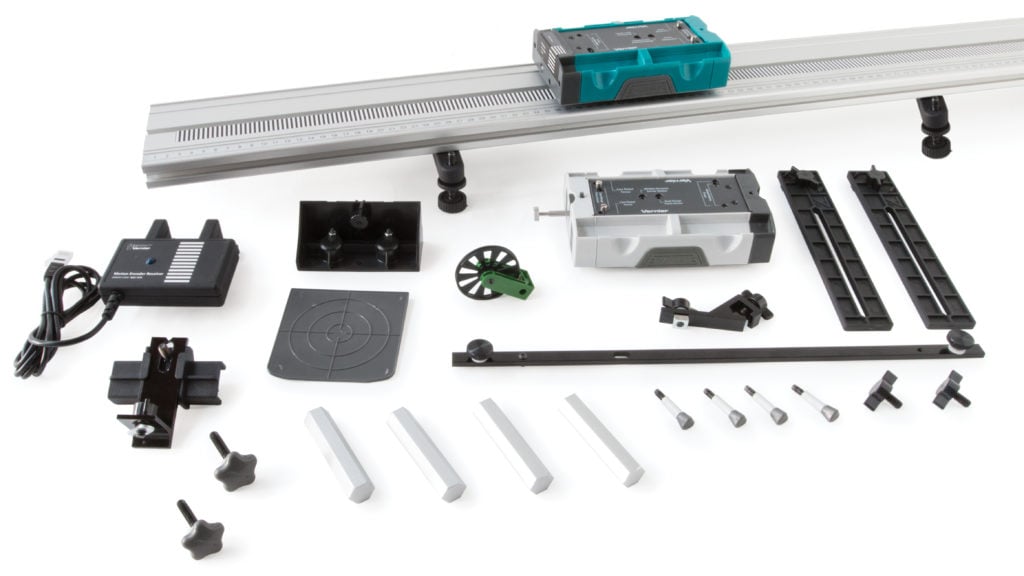
What's Included
- Motion Encoder Cart with 2 magnetic and 2 plain collision tabs (requires 2 AAA batteries, not included)
- Motion Encoder Receiver
- Plunger Cart with 2 magnetic and 4 plain collision tabs
- Cart Masses (4) – 125 g
- Combination 1.2 m Dynamics Track/Optics Bench with encoder strip*
- Adjustable Leveling Feet (2)
- Mounting hardware for Dual-Range Force Sensor and Low-g Accelerometer (2 large bolts and 4 small bolts)
- Adjustable End Stop
- Motion Detector Bracket
- Motion Detector Reflector Flag with 2 magnetic collision tabs
- Photogate Brackets (2)
- Rod Clamp
- Allen wrench 3/32 inch
- Ultra Pulley
- Pulley Bracket
*The Dynamics Cart and Track System with Motion Encoder and Long Track includes the parts listed above but substitutes a 2.2 m track for the 1.2 m track.
Compatible Software
WARNING: The Motion Encoder Receiver is not compatible with the Texas Instruments TI-Nspire Lab Cradle. Connecting the Receiver to the Lab Cradle will render the Cradle inoperative, requiring repair by Texas Instruments.
Getting Started
- Attach the receiver to the end of the track, matching the encoder strip on the track to the markings on the receiver.
- Place the track on a level surface.
- Insert two AAA batteries (not included) into the encoder cart.
- While the battery compartment is open, move the switch to the appropriate distance for the track you are using. Use 1 m for the 1.2 meter track, and use 2 m for the 2.2 meter track.
- Connect the receiver to the interface (LabQuest 3, LabQuest Mini, etc.). Launch the data-collection software (Vernier Graphical Analysis® or LabQuest® App).
- Turn on the cart by pressing the power button. It will glow blue when the cart is on.
- Place the cart on the track, wheels in grooves, with the blue light facing the receiver.
- Begin data collection, and let the cart roll.
Need additional information?
Visit the following link:
Calibrating the Sensor
Calibration of the Motion Encoder System is not necessary nor is it possible. The printed bars on the track determine the scale, and the cart encoder counts the passage of the bars. Available units are meters and feet, selectable in the software.
In contrast, it is possible and desirable to zero the encoder. Unlike an ultrasonic motion detector, there is no way for the system to have an unchanging reference position; it can only count bars from the point at which the cart is placed on the track. As a result, you may want to move the cart to the receiver end of the track and zero the reading in the software.
The positive direction can be reversed so that readings increase as the cart moves toward the receiver. A reversed coordinate system is helpful when using two Motion Encoder Systems to monitor the motion of two encoder carts, so that the positive direction is the same in both cases. (Note: additional hardware not included with the system is required to use two Motion Encoder Carts on the same track.)
Because the encoder strip must be continuous, the Motion Encoder System cannot be used with a Track-to-Track Coupler.
Specifications
|
Measurement Range 1 m range 2 m range |
1.2 m track 2.2 m track |
|
Accuracy and Resolution |
1 mm |
|
Temperature range |
5 to 80°C (readings not compensated) |
|
Optimum data-collection rate |
15–30 Hz |
Care and Maintenance
Do not wrap the cable tightly around the motion encoder receiver for storage. Repeatedly doing so can irreparably damage the wires and is not covered under warranty.
Do not use an alcohol-based cleaner on the track, as this will remove the ink from the encoder strip and centimeter scale on the track.
How the Sensor Works
Power
The Motion Encoder Cart requires two AAA batteries. Either NiMH rechargeable batteries or alkaline disposable batteries can be used. Turn on the cart by pressing the clear power button on the cart endcap. It will glow blue when power is on. Press again to turn off. The cart will turn itself off after 20 minutes of inactivity. However, any motion on the track will cause the timer to reset. The receiver is powered by the data-collection interface.
Battery life depends on use and the range setting. Low battery level may cause erratic detection of the cart motion, including incorrect velocity signs. Replace the batteries if this is seen.
Range Setting of the Motion Encoder Cart
The IR transmitter on the cart has two power levels available. The default 1 m setting conserves battery power. If the cart is used on a 2.2 m track, set the cart to the higher 2 m power level. If the high-power setting is not used on a 2.2 m track, the receiver will not reliably sense the position of the cart at the far end of the track. The switch is located inside the battery compartment.
Use of Two Vernier Motion Encoder Systems on the Same Track
Some experiments require measuring the motion of two carts. This can be done by purchasing the Motion Encoder Cart and Receiver (order code DTS-MEC) to add a second encoder cart, receiver, and strip to your Vernier Motion Encoder System. A Motion Encoder Receiver is placed at either end of the track, and two Motion Encoder Carts are used on the track, each with its transmitter facing the unobstructed receiver. A second encoder strip must be applied to the track, resulting in one on either side of the center slot.
Consider reversing the direction of one receiver so that the same direction is positive for each system. Put the carts together, and zero both systems. This will put the carts on the same coordinate system; if they move together in contact, their position readings will be the same.
Use of Multiple Vernier Motion Encoder Systems in the Same Room
Because of the narrow IR beam used for signaling between the cart and receiver, interference should be rare. However, if one apparatus is apparently interfering with another, the problem can be resolved by repositioning one of the tracks.
All Motion Encoder Carts are interchangeable; that is, there is no required matching of cart to receiver.
Data-Collection Notes for the Motion Encoder System
- The optical motion encoder can only make relative position measurements, so the zero point is initially determined by the location on the track that the cart is first placed when the power is on. If you want zero to be near the receiver, initially place the cart next to the receiver. This behavior is very different from the ultrasonic motion detector, which by default uses a fixed origin near the detector.
- The motion encoder is nearly immune to interference, but it cannot work if the IR beam between the cart and receiver is blocked. Keep your hand away from this region.
- Since the zero position (origin) of the encoder depends on where the cart is placed initially, it is often useful to zero the encoder in the software. Place the cart in the position that you want to declare as zero. To zero the position of the sensor cart, click or tap the position meter and choose Zero.
- It can also be useful to reverse the direction of the coordinate system, so that values increase as the cart moves toward the receiver. To reverse the reading of the sensor cart position, click or tap the position meter and select Reverse.
- High data-collection rates are not useful for the motion encoder. Rates above 30 Hz will produce noisy velocity and acceleration graphs because the cart may appear to be at one position for several time measurements.
- Just like the ultrasonic motion detector, it can be useful to adjust the number of points used to calculate derivatives for velocity and acceleration graphs. Higher values create quieter graphs, while lower values result in more temporal detail. In LabQuest App, adjust this value by selecting Settings from the File menu. In Graphical Analysis, adjust this value by selecting Session Preferences from the Overflow menu.
Adjustable Leveling Feet
The Adjustable Leveling Feet slide into the end of the track, with the nut in the center slot of the track underside. Adjust the height as desired, then adjust the washers until they are flush against the horizontal piece of the foot assembly.
Photogate Bracket
Photogate Brackets attach to the side of the track. With the nut loosely on the T‑handled bolt, slide the nut into the side channel of the track. Attach the photogate using the supplied wing bolt in the long slot. Adjust the gate height so the beam intercepts the desired portion of the target. For a video showing this, see www.vernier.com/til/17104
Motion Detector Bracket
Although we expect that the motion encoder will be used most often to record motion data, it is also possible to use the Dynamics Cart and Track System with an ultrasonic motion detector.
Any Vernier motion detector can be attached to the supplied Motion Detector Bracket. The Motion Detector Bracket has a pin to locate motion detectors having a hinged head on the bracket. There is a knob, nut, and bolt to attach the bracket to the track center groove, and a threaded hole at the end near the pin for attaching the motion detector.
See www.vernier.com/til/2426 for details on using the Motion Detector Bracket. When the motion detector is not attached to the bracket, its mounting screw can be stored in the threaded hole near the pin.
Most Vernier motion detectors can be placed so that the sensor is 15–20 cm from the end of the track. The carts can then be detected properly all the way to the end. The cart mode is appropriate for the dynamics system. Older motion detectors that lack a range switch can still be used, but the carts must remain beyond the 45 cm minimum working distance of these older sensors.
Motion Detector Reflector Flag
Some users prefer to enhance the reflectivity of the cart when using an ultrasonic motion detector. Use of the Motion Detector Reflector Flag makes the position of the detector less critical, but its use is optional.
The Motion Detector Reflector Flag attaches to the dark gray end of a cart. Insert magnetic collision tabs and snap the flag against the end of the cart, with the metal inserts against the magnet tabs. Place the cart on the track with the flag toward the motion detector.
Adjustable End Stop
The Adjustable End Stop slides into the top slot from the end of the track. Adjust the position as desired. Insert magnets in the End Stop if desired (see www.vernier.com/til/2184). The End Stop cannot be used at the same end as a motion detector or Motion Encoder Receiver.
Rod Clamp
The Rod Clamp is used to support the track with a user-supplied ring stand. A 12 mm rod is the maximum size accommodated. Insert the Rod Clamp nut into the side of the track. Adjust the height as desired. See www.vernier.com/til/15793
Mounting Hardware
The supplied mounting hardware is used to attach sensors to the cart, such as a force sensor, accelerometer, or Wireless Dynamics Sensor System (discontinued).
Additional Mass
The four 125 g masses are used to change the mass of the cart for dynamics experiments. The cart mass is a bit more than 250 g, but additions such as magnets, hook-and-pile tabs, sensors, and the encoder system will increase the total mass. As a result, it is best to weigh the cart as used when the mass is important.
The four masses can be used one at a time or in combination on either cart. The mass trays on the sides allow the addition of masses without removing sensors. It is not necessary to keep the carts balanced with the same mass on each side.
Pulley Bracket and Pulley
The Pulley Bracket and Pulley can be attached to the end of the track to create a modified-Atwood machine using user-supplied masses and string. It can be assembled with or without a Photogate for motion measurement.
Insert the oblong nut into the bottom slot of the track and tighten. To attach the pulley without a Photogate, use the short bolt to attach the pulley. Adjust the height of the pulley as needed to keep the string level. To include a Photogate, slide the plastic photogate mount over the vertical portion of the Pulley Bracket, with the open slot outward and upward. Insert the Vernier Photogate into the mount, and pass the long bolt through the bracket, and Photogate, capturing the threads of the bolt with the Pulley. See www.vernier.com/til/15443 for a video showing installation.
To include a Photogate, see www.vernier.com/til/2076 for a video showing installation.
Collision Tabs
The Vernier dynamics carts are supplied with magnets and hook-and-pile tabs. These parts are attached using removable Collision Tabs. Since the magnets may interfere with certain experiments using force sensors on the carts, only install the magnets if you need them.
The magnets are useful in studying collisions with the magnets positioned so that they are the same polarity on both sides and on both carts. This way the carts will repel one another, and you can arrange a contactless collision in which the carts never actually touch. The collision will be very nearly elastic, much more so than a collision using a spring or any kind of contact.
The removable Collision Tabs have two sides. One is marked N, and the other is plain. The plain side is for use with hook-and-pile material on tabs without magnets.
The Collision Tabs can be inserted either way, exposing or concealing any hook‑and‑pile material. To quickly perform an experiment without magnets, remove the Collision Tabs.
The Adjustable End Stop will hold magnets as well. Note that only low-speed collisions with the End Stop will keep the cart on the track. For instructions on installing magnets in the end stop, see www.vernier.com/til/2184
To study totally inelastic collisions, place hook-and-pile tabs on the Collision Tabs without magnets. Looking at the end of the cart, place a hook pad on the left-hand plug, and a pile tab on the right-hand side. Center the pad on the round part of the Collision Tab. This way any cart with hook-and-pile tabs will stick to any other. Hook-and-pile equipped carts will stick together, creating a totally inelastic collision.
Plunger Cart
One cart includes a spring-loaded plunger for collisions. To use the plunger, simultaneously press the horizontal button above the plunger and press the plunger in until it locks. To release, press on the pin from the top of the cart. The plunger force can be adjusted by rotating the plunger while it is extended. An uncalibrated scale is visible on the underside of the cart. Use this scale to return to a previous setting.
The Plunger Cart is capable of superelastic collisions. To enable this mode, use a small screwdriver to unlock the dark gray plastic plug below the main plunger. Depress the plug using the screwdriver and rotate one-half turn counterclockwise to unlock. The plunger will extend about 2 mm.
Lock the plunger as before to prepare for a superelastic collision. In a collision, the plug will strike first and trigger the release of the plunger.
To disable superelastic collision mode, use a small screwdriver to depress and rotate the plug one-half turn clockwise. It will lock in the flush position.
The plunger cart is a bit more than 250 g. Adding accessories such as sensors or magnets will change the mass.
Note: The plunger cart does not come with the motion encoding functionality built in. To add that functionality, you can purchase the Motion Encoder Cart Upgrade Kit (order code: DTS-MEU).
Use of Additional Accessories and Sensors
The following examples show various sensors attached to a Vernier dynamics cart. Sensors are not included with the Dynamics Cart and Track System with Motion Encoder.
Attach a force sensor
1. Place the sensor over the two silver pins as shown on the cart top sheet. Older force sensors may require moving the pins to the wide spacing option.
2. Use the large bolt to secure the sensor to the cart. For detailed instructions on how to do this, see www.vernier.com/til/3974
3. Configure the force sensor as needed with a hook, bumper, or magnet.
Attach the Low-g Accelerometer (LGA-BTA)
1. To attach an accelerometer, place the sensor over the mounting holes as shown on the cart top panel.
2. Use two small mounting bolts to secure the sensor as shown.
Attach a force sensor and accelerometer in combination
The Dual-Range Force Sensor (order code DFS-BTA) and the Low-g Accelerometer (LGA-BTA) can be used simultaneously using the same procedures. When using a Go Direct Force and Acceleration Sensor (order code GDX‑FOR) you need only the one sensor. To get both force and acceleration measurements, activate both the Force channel and the X-acceleration channel in the data collection software.
Attach a Cart Fan
The Cart Fan (order code: DTS-CFAN) can be used to provide a constant force for kinematics and dynamics experiments.
- Use two half-inch 10-32 screws (included with the cart fan) to connect the Mounting Plate to the Low-g Accelerometer holes on the cart surface. For additional security, use the half-inch ¼"-20 screw (also included) to connect the Mounting Plate to the DFS hole.
- Insert the Cart Fan(s) into the appropriate mounting position(s) for your experiment. The Cart Fan can be mounted pointing forward or backward. The mounting bracket can be pointed off axis in 15 degree intervals.
General Tips for the Vernier Dynamics Cart and Track System
- Do not install the magnets unless you know you want to use them. They will interfere if you perform an experiment with a force sensor riding on the cart, since the force sensor will then not read the total force acting on the cart.
- The magnets are designed for fairly gentle collisions. If the cart is moving too quickly, the magnetic forces may cause the cart to jump off the track to the side. If this happens, use a lower initial velocity for the cart.
- Keep the track clean; if it is dirty, the carts will not roll smoothly. However, do not use an alcohol-based cleaner, as this will remove the ink from the centimeter scale on the track.
- Use lower speeds and lower inclines than you might initially choose; the physics is the same and students will have more time to observe what is happening.
- Attach the track feet, sliding at least one in about 30 cm before inserting the Motion Detector Bracket.
Suggested Experiments
The Vernier Motion Encoder System can be used wherever a motion detector could have been used with a cart and track. The encoder depends on the presence of the track, so that only cart and track experiments can be performed.
Measure Cart Acceleration
The basic motion of a cart on a ramp can be studied. For example, perform Experiment 3 from Physics with Vernier, “Cart on a Ramp.” Alternatively, repeat Galileo’s experiment of determining g using an object and a ramp. This is Experiment 4, “Determining g on an Incline,” from Physics with Vernier.
Newton’s Second Law
Use a force sensor on the encoder cart to record both applied force and acceleration. The two will be proportional. Alternatively, set up a modified‑Atwood machine with a hanging mass and a pulley at the track end opposite the receiver. Measure the acceleration of the encoder cart as a function of the hanging mass.
Measure Fan Cart Acceleration
Add an Encoder Fan Cart (order code CART-FEC) or a Cart Fan (order code DTS-CFAN) to observe the motion of a cart under constant thrust.
Measure Cart Acceleration with Friction
Add a Friction Pad (order code DTS-PAD) to the encoder cart and observe the motion of the cart with varying frictional forces.
Momentum-Impulse
Add a force sensor and a Bumper-Launcher Kit (order code BLK) to observe the relationship between momentum and impulse. Find the impulse by integrating under a force vs. time graph.
Conservation of Energy
Use two Vernier Motion Encoder Systems or a Motion Encoder System plus a motion detector to observe a change in energy due to a two-cart collision.
Conservation of Momentum
Use two Vernier Motion Encoder Systems or a Motion Encoder System plus a motion detector to observe a change in momentum due to a collision between two carts. Try different kinds of collision: elastic, inelastic, totally inelastic.
Accessories
| Item | Order Code |
|---|---|
| Bumper and Launcher Kit | BLK |
| Cart Fan with Mounting Plate | DTS-CFAN |
| Encoder Fan Cart | CART-FEC |
| Motion Encoder Cart and Receiver | DTS-MEC |
| Friction Pad DTS | DTS-PAD |
| Eddy Current Brake | DTS-ECB |
| Motion Encoder Cart Upgrade Kit | DTS-MEU |
| Optics Expansion Kit | OEK |
| Mirror Set for Optics Expansion Kit | M-OEK |
| Diffraction Apparatus | DAK |
| Polarizer/Analyzer for Optics Expansion Kit | PAK-OEK |
| Color Mixer Kit | CM-OEK |
| Hanging Mass Set 250 g | PHY-HM250 |
Replacement Parts
| Item | Order Code |
| 1.2 m Dynamics Track | TRACK |
| 2.2 m Dynamics Track | TRACK-LONG |
| Motion Encoder Cart Receiver | MEC-BTD |
| Motion Encoder Cart | DTS-CART-MEC |
| Plunger Cart | DTS-CART-P |
| Motion Encoder Long Track Strip | METS-LONG |
| DTS Cart Masses (4 Hexagonal) | DTS-MASS |
| Ultra Pulley Attachment | SPA |
| Pulley Bracket | B-SPA |
| Rod Clamp | RC-VDS |
| Motion Detector Bracket | DTS-MDB |
| Motion Detector Reflector Flag | DTS-FLAG |
| Photogate Bracket | PGB-VDS |
| Adjustable End Stop | AS-VDS |
| Adjustable Two-Foot Leveler | AL-VDS |
| Dynamics Cart Replacement Tabs | DTS-TABS |
| DTS Fasteners for Force Sensor and Accelerometer | DTS-ACC |
| Anti-Roll Pegs (10 Pack) | VDS-ARP10 |
Troubleshooting
For troubleshooting and FAQs, see www.vernier.com/til/3153
Repair Information
If you have watched the related product video(s), followed the troubleshooting steps, and are still having trouble with your Vernier Dynamics Cart and Track System with Motion Encoder, contact Vernier Technical Support at support@vernier.com or call 888-837-6437, or contact us using the chat on our website, www.vernier.com. Support specialists will work with you to determine if the unit needs to be sent in for repair. At that time, a Return Merchandise Authorization (RMA) number will be issued and instructions will be communicated on how to return the unit for repair.
Warranty
Warranty information for this product can be found on the Support tab at www.vernier.com/dts-ec/#support
General warranty information can be found at www.vernier.com/warranty
Disposal
When disposing of this electronic product, do not treat it as household waste. Its disposal is subject to regulations that vary by country and region. This item should be given to an applicable collection point for the recycling of electrical and electronic equipment. By ensuring that this product is disposed of correctly, you help prevent potential negative consequences on human health or on the environment. The recycling of materials will help to conserve natural resources. For more detailed information about recycling this product, contact your local city office or your disposal service.
Battery recycling information is available at www.call2recycle.org
Do not puncture or expose the battery to excessive heat or flame.
 The symbol, shown here, indicates that this product must not be disposed of in a standard waste container.
Contact Support
Fill out our online support form or call us toll-free at 1-888-837-6437.